Wednesday, August 19, 2009

Lexus Install - Installing a Xenarc Technologies In-Car 7 inch Automotive Grade Monitor Overview

If you're looking to buy the IS300 Nav housing yourself, then these are the parts you will need:

Factory Housing: (minimal - non-motorized version)
-55443-53020 Cover, Display Door (~$30)
-55682-53010 Right Gear (~$20)
-55681-53010 Left Gear (~$20)
-55683-53020 Bottom Support (~$25)
-55479-53020 Trim (Screen casing) (~$40)
Needed only for models 2003 and below:
55662-53010 Trim (Air-vent dash tray) (~$60)

If you call a Lexus dealership, they'll charge over $300 for these parts. However, I found someone recommending a guy named Leroy at Nalley Roswell Lexus Parts who will give a nice discount of all nav parts bringing the total to a nice $150. (I expect it's because of all the business he's getting from geeks like us installing computers in their cars.) Anyway, I recommend giving him a call: Leroy (678) 795-2050

As for bolts and screws, you'll need these parts from Home Depot

-Threaded Brass/Metal Rod (thinnest one available) 1 foot
-Machine Screw Nut #6 – 32
-Machine Screw and Nuts #4 – 40 x 3/8”
-Metal Screw #8 x 5/8”


Lexus Install - Installing a Xenarc Technologies 7 inch Automotive Grade Monitor Overview


I wanted the best monitor possible, since what's the point of building a carputer if I can't even use it? From what I read on mp3car.com and the like, Xenarc makes the best one. Also, at the time I wasn't sure if I should get it touchscreen or not. In case you're debating the same thing for your install, let me just say...GET IT! I don't know how I would have done anything without a touchscreen. It's a no-brainer really, I'm kind of embarresed I even spent time thinking about it. So I went ahead and bought the Xenarc 700TSV.

Lexus Install - Installing a Xenarc Technologies 7 inch Automotive Grade Monitor Overview 
Lexus Install - Installing a Xenarc Technologies 7 inch Automotive Grade Monitor Overview

My only concern with the Xenarc was whether or not it would fit inside the factory nav housing I bought from Lexus. I read some posts on http://my.is of people installing other monitors, but never a Xenarc. And the only way to see if it would fit is by taking apart the monitor, which obviously voids the warranty. Anyway, I was in luck, the monitor JUST BARELY fit into the housing. So I was a happy camper.


One problem I ran into while installing it into the housing was how to keep it pressed up tightly against the housing? After all, I will be poking and pushing at it with my fingers. There's also no good place to put tape around the housing in order to strap it down. What I did was stick a pencil up behind it. I was actually able to get it sorta wedged up in between the housing and the back of the monitor. That and some tape (where I was able to put it) has done the job rather nicely.

Another issue I had was how to get the monitor to stay up. After all, the housing was made for the screen to close and open. And since all the weight for the screen is in the front, it's "natural" position is closed. How I solved this issue was by placing some pieces of felt on the side of the housing. This way it holds the screen upright but if I apply a little force, it'll close as well. It took a bit of adjusting to find the perfect placement for the felt so that the screen is at a prime viewing angle, but I got it working and that's what counts. In the future, I do hope to motorize it (someday).

Here are some final shots of the Xenarc inside the nav housing


Since this was the first time I've ever done anything remotely electrical before, I was kind of intimidated. I had no idea as to how I would hook this up to the battery of my car, what wires I needed, what kind of fuse, etc etc. I had a friend who actually came to help me out on this. Since he had already has a carputer, I figured it wouldn't be a prob at all. Let me just say this, after it's all said and done, it's really not that difficult at all and I could have easily done it myself had I known which wires to buy and what size fuse I needed.

In order to get the audio into the car speakers, I needed to tap into the factory wires behind the stereo. The reason for this is because I didn't want to use any crappy FM transmitter, and I didn't want to replace the stock amp or speakers. And most importantly, I wanted to be able to control the volume of the computer though the normal volume knob. So I decided to add a relay switch into the wires headed from the radio to the amp. Although I'm actually only writing about this now, this was actually the first thing I actually did on my car. Only 4 months later did I actually install the final computer. In the interim, I had my ipod hooked up to make good use of the aux-in. I found two great threads on how create an aux-in which I followed word-for-word on.

http://my.is/forums/showthread.php?t=220767

http://my.is/forums/showthread.php?t=253814

(the 2nd thread seems to be down, which is sad cause that was the one that showed me how to install a relay switch so I can toggle between the computer and radio). Here's a shot of the switches (my car doesn't have seat heaters so I already had the location planned out).


The switch on the left toggles the audio and the one on the right will be used to send the signal to the Opus. I figured sometimes I wouldn't want the PC to turn on (say I'm just moving my car cause of damn street cleaning). If I keep the switch in the off position, it'll either hibernate the PC or just not turn on once I start the engine. After installing it, I'm totally glad I added this switch and advise everyone else to do the same. It's great for when you give your car to the valet or bring it in for an oil change.

Again, I had no electrical experience before (I never even used a soldering iron before this) and although it took me a few hours, it wasn't too difficult at all. Oh, one thing I needed to buy was a "ground loop isolator." Since I wasn't able to ground all the wires at the same point, I had some interference, especially whenever I hit the accelerator. I bought mine at radio shack and now there's no problem at all! 

Anyway, now it was time install this bad boy. The first wall I ran into was how would I run the wires from the battery to my glovebox. I was mentally preparing myself to drill through the firewall but I really wasn't too keen on that idea. After inspecting my car, I noticed there was already a hole cut out for the air condition exhaust. It worked perfectly! I was able to squeeze in through that hole without drilling any additional holes in my car. Actually, the only piece of my car which is "damaged" is the glove box since I had to cut the back of it out. Here you can see the power wires (thick red ones) as well as all the others.


The one thing which was great about install the carputer in the glove box, as opposed to the trunk as I see so many people doing, is that it was so easy to run all the wires. The battery is right there. The monitor is right there. And even the audio wires simply ran behind the console. It was actually surprisingly easy to plug everything into each other.

Here's everything nice a snug in the glove box.


Here's the cover loosely set ontop of the glove box. (it fits a lot tighter once I tie it down.


The rest was really a snap. I just stuck the monitor in place.


And then it was done! Behold, my very own Lexus PC Carputer. Complete with Navigation, MP3s, Divx, DVDs, Bluetooth, Internet, and Nintendo! As for the GPS antenna, I just placed it on top of my dash (all the way on the right) and ran the USB wire through the passenger door and into the glovebox. It's a perfect location since the antenna has line-of-sight, it's in an inconspicuous place, but most importantly, it was so easy to place it there! I didn't have to drill any holes into my dash. The wire is easily hidden by that rubber rain-protector thing (i think that's the official name). Anyway, here are some final pictures of the install:


As for future updates, I still have not installed Phoco or any other phone program (as of Jan 07), but I definitely plan to soon. I already have the bluetooth link which I use for connecting to the internet. And after seeing a friend talk into his car and hearing the call through the audio of the speakers....damn! It's for sure my next project (if I can find the time).

Please feel free to ask me any questions you have or even to simply leave feedback. The original thread is on Mp3Car.com and can be found here: http://www.mp3car.com/vbulletin/showthread.php?t=85631 (although this site is FAR more detailed with a lot more pictures). The thread is simply an overview of what you just read.

Also, if you enjoyed reading this write-up and if it helped you in any way, please click on some banner ads! It's the least you can do, right? :-)


HELPFUL LINKS
Compare ALL Xenarc 7" to 18" Monitors 

"HDMI Monitors"
"7" HDMI Monitors"
"8" HDMI Monitors"
"9" HDMI Monitors"
"10" HDMI Monitors"
"12" HDMI Monitors"
"15" HDMI Monitors"
"18" HDMI Monitors"

"SDI Monitors"
"7" SDI Monitors"
"8" SDI Monitors"
"9" SDI Monitors"
"10" SDI Monitors"
"12" SDI Monitors"
"15" SDI Monitors"
"18" SDI Monitors"

"VGA Monitors"
"7" VGA Monitors"
"8" VGA Monitors"
"9" VGA Monitors"
"10" VGA Monitors"
"12" VGA Monitors"
"15" VGA Monitors"
"18" VGA Monitors"

"DVI Monitors"
"7" DVI Monitors"
"8" DVI Monitors"
"9" DVI Monitors"
"10" DVI Monitors"
"12" DVI Monitors"
"15" DVI Monitors"
"18" DVI Monitors"

"Displayport Monitors"
"7" Displayport Monitors"
"8" Displayport Monitors"
"9" Displayport Monitors"
"10" Displayport Monitors"
"12" Displayport Monitors"
"15" Displayport Monitors"
"18" Displayport Monitors"


Sunday, November 13, 2005

Mac Mini Carputer Install - Mazda 3 Using the Xenarc 700TSV 7" touch screen Automotive Grade Display Touchscreen monitor

This page documents my installation of a Mac Mini into the glove box of a 2005 Mazda 3 sedan. My goals of this project were to create a system with better than stock sound and capability, while maintaining a clean, stock appearance. The information found in mp3car.com, macvroom.com, and mazda3forums.com was a huge help and made this project so much easier.
System components:

* Mac Mini, 1.25ghz G4, 512meg ram, 40 gig HD, OS X 10.3 Panther
* Built in Bluetooth and Airport Extreme (wi-fi) cards
* Carnetix CNX-P1900 power supply with CNX-P5V additional 5v output
* Xenarc 700TSV 7" touch screen monitor
* Belkin 4 port USB 2.0 powered hub
* Griffin RadioSHARK radio module (modified)
* Griffin PowerMate USB volume control knob
* USGlobalSat BU-353 USB GPS Receiver (on its way to me)
* NO stereo head unit
* Kicker KX-200.4 4 channel amplifier, installed under driver's seat
* Kicker KX-250.2 2 channel amplifier, on back of rear seat in trunk
* Kicker Solo Baric 10" L5 Subwoofer, dual 2-ohm voice coils wired in series
* Kicker single 10" vented enclosure
* Apple wireless bluetooth keyboard and mouse
* Metra radio install kit for Mazda 3 (99-7504), modified for use as screen bezel
* Metra radio wiring harness/plug (70-7903)

Overall System Diagram:


Here is a fairly complete photo walkthrough of my install process. 

Let me start first by saying I LOVE this car. This is the 2005 Mazda 3, Sport trim, 2.3L 4 cylinder engine, 5 speed manual transmission. It has the combination of looks, power, handling, and economy that I was after. It feels great to drive, and handles nicely - like it's on rails. After buying it at the end of Summer '05, I decided I needed to plan some modifications. I started with a window tint and alarm to help protect whatever goodies were to come later. Then I started researching Carputers, and stumbled across postings showing the Mac Mini being installed in cars, specifically the Mazda 3. Having not used an Apple since high school, I decided to just jump in and go for it! 

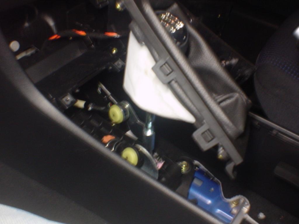
Just start pulling your car apart. Here I've pulled straight up on the cupholder assembly, carefully separating the clips. There are no screws until you get up to the cigarette lighter panel. I used the empty space below the center console to run my signal cables to the Kicker KX-200.4 4-channel amp under the driver's seat (not pictured). 

The shift boot cover pulls up easily as well. Don't bother removing the shift knob. Just pull the whole boot up and out of the way. This will expose the two screws that secure the cig lighter panel. Take those loose and lay the panel aside to see what lurks behind. 


Now the cig panel has been layed aside and dangling by its wires. 


This is where I had originally hoped my Mac Mini could go. It appears to be too small a space for it. At a minimum, you'd need to dremel off those mounting brackets on the sides of the space to even let the Mini fit between. I just don't see how it would fit in there. I've seen some pics of folks putting in a head unit there, so if you are not concerned about hacking up your car then it might still be doable. I decided to go with the simpler glove box install. 


Here's another look at this space. I decided not to do anything at all back here.


It's very easy to get your stock radio out. Gently pull out the carbon fiber deco trim, starting in the middle, then the left side, and finally pull the whole strip towards the left to clear the hook on the right side of the dash (sorry, no picture). This exposes the screws that hold in the radio and the vent cover. Just remove the screws. The radio can then be pulled straight out, leaving this vast space. You'll of course need to remove the big white plug (squeeze the little release tab firmly and pull straight out) and also the radio antenna plug (pull straight out while gently turning). 


Look at all this room. I knew of course that I wanted my 7 inch xenarc screen to go right behind the carved-up Metra dash bezel. That leaves plenty more space behind the screen, so I just put my Carnetix P1900 power supply here - tie-wrapped to that bracket in the back. 


After removing the two screws, the vent cover simply pulls up and out - gently pull to release the clips. This exposes a bit of space above the vent holes where you can store USB components. I don't see how some folks have had room here to install a flip up monitor. Just doesn't seem possible without hacking the vents. 


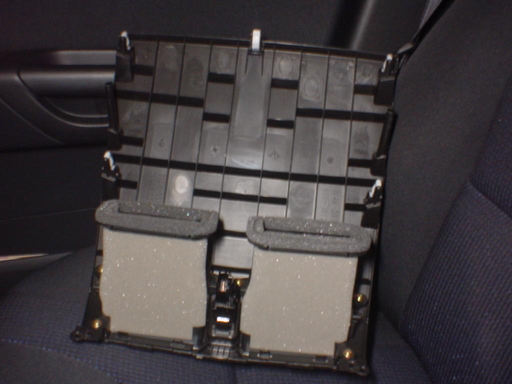
Here's a shot of the underside of the removed vent cover. 


Test-fitting the Metra double-din kit (99-7504). I didn't really try to make this part of the job real pretty. Just dremeled out the whole bottom tray and middle cross-member. Someday perhaps I'll try to bondo it or something. 


Here's a trial fit of the monitor standing just behind the Metra bezel. It won't quite fit at this point. The brackets at the bottom of this open space had to be clearanced a bit with the dremel to let the bottom corners of the monitor slide in between. 


So this seems to be an easy way to mount the monitor securely in this space. I had seen a similar install so I don't claim this as my own idea. There are two screws in there on each side of the space. I just made a bracket using a piece of aluminum bar stock that I had laying around. Just drill holes on either end, and one in the center. I used a 2 inch thin bolt to connect to the back of the monitor, and a thick piece of stiff packing foam material between the monitor and bracket since the bracket doesn't line up flush with the back of the monitor. 


I did not take a measurement but it's easy to BS a bracket like this. 


I highly recommend the use of this wiring harness if you plan to completely remove your stock head unit from your Mazda3. This is Metra's 70-7903 plug. The label shows 2002 Mazda Protege, but it works for all the Mazda3 models as well. I got mine locally for $15.00. It makes sense not to hack on the car's stock wiring. Make your speaker connections on the pigtails on this plug instead. That way if you ever need to go stock, you just unplug this harness and replace your old stereo. 


Basically the pairs of wires you see on the bottom row of the harness are to be connected to each channel of a 4 channel amp (or head unit, if you are keeping it with no amp). Then, on the top row, the black wire is ground; the red wire is IGNITION (on when the key is turned on); the orange wire is...something I found I didn't need so I yanked it out; and finally, the yellow wire is constant 12 volt positive. I only used the ignition and constant 12v connections for making a 3-way valet switch to control the state of the mac mini. The brown and blue wires in the middle were also removed from this harness as I did not use them in my setup. 


I decided to use the power feed from the Metra harness to feed my valet switch that controls the sleep mode of the Carnetix. Here I'm soldering on the connections. 


Closeup of the wires. You can make out the markings that Metra conveniently places on each wire. 


I used a 3-position DPDT switch to give me some control over the sleep state of the Carnetix and Mac Mini. The top wire is connected to the RED ignition power wire on the Metra harness. The middle wire goes to the Carnetix ignition wire input. The bottom wire goes to the YELLOW constant power wire on the Metra harness. As installed, if the switch is in the middle position, then the center wire stays at 0 volts, therefore telling the Carnetix to sleep the Mac. In the downwards position, the car's ignition state will control the Mac's sleep state. In the upwards position, the Carnetix is getting constant 12v on the ignition wire (regardless of actual ignition state) so you can run the computer even with the car off. I do this when I want to sync my iTunes over my wireless network. I've run the comp for 4+ hours in the garage with no engine running and no ill effects on the battery. I am not having luck controlling based on ignition state. If the mac is sleeping when I start the car, the mac is rebooted. But if the mac is awake, it stays stable during engine crank. Maybe I've got something set wrong on the Carnetix. Not too worried about it at this point.


I didn't get good shots of me hacking up the Mac Mini DC cable. I just cut off most of the cable (between Mac Mini and the converter brick), stripped back the sheath, and separated out the 3 connections on this cable. The braided sheath is gathered up and tied in with the black ground wire, then soldered to the output ground wire on the Carnetix. The grey iSense wire goes to the white wire on the Carnetix, and of course the red wire goes to Carnetix red wire. Sorry, no picture of this connection. The separate black cable is for the Mac Mini power button connection. These two leads go to the appropriate connections on the Carnetix. The other end connects up to the special Y-adapter and extension cable for the Mac Mini power button, provided by mp3car.com. 


Here's the business end of the Mac Mini power cable. The other end of the power button cable is shown - I just used a standard RCA cable to connect to a female jack onto the Mac Mini button extension cable (shown in next pic). 


Here is the female RCA jack, which is soldered onto the power button extension cable. This connection allows the Carnetix power supply to send the Mac Mini a power button signal to sleep and wake it up.


The moment of truth - the first test of power supply, Mac Mini, and Xenarc 700TSV monitor, being powered off the car's battery! The Mac Mini has built in bluetooth and Wi-Fi, so I pulled up mp3car.com using the Safari browser. That blue wire coming out of the Carnetix is the amp control wire. I ran this to the REM connectors on both amps so that when the Carnetix wakes up the Mac, it also wakes up the amps. I must say that the Carnetix P1900 power supply is very impressive and makes this install very easy! 


This shot was taken to remind me how much of the dash was disassembled during this install. 


I am very happy with the Xenarc 700TSV monitor. 

After carefully routing the wires to the back of the glove box, it's finally installed!! I did have to remove the glove box to feed the wires to the back. Just remove the square knock-out plate back there and you've got a plenty big hole for the wiring. 


Right now, the Mac is just sitting in there with no securing mechanism. It doesn't move around much due to the nice rubberized base. You could just use some velcro if you're worried about it sliding.

Testing out the CCarProject interface. It doesn't appear to be completely working, and it won't play any of your purchased iTunes songs. I do like the way the buttons are laid out though. Maybe a completed version will be available someday. 


Here I'm playing Pixar's 'For the Birds' video using iTunes. You can also throw this video into full screen mode. 


The screen is fairly easy to see even in daylight. 


The control buttons for the monitor are positioned slightly below the bottom edge of the Metra bezel. I just use the screen's included remote to access the screen's menu. 


The trunk was the last step of my install. I went with a Kicker KX250.2 amplifier, which is a 2-channel amp. This amp drives a single 10" Kicker Solo Baric L5 sub. The sub has two 2-ohm voice coils, wired in series, to present 4 ohms to the amp output, bridged to mono. The sub is enclosed in a nice and heavy bandpass enclosure. The opening is not seen in these pics, but it opens to the back of the car, which was recommended by the shop where I bought this enclosure. I was not familiar with a sideways install like this but I really do like having the optimal remaining trunk space. I took my time and carefully routed the wires under the carpet on the back seat for a clean install. The bass hits hard and clean! 


Close-up of the sub. I do like the way the enclosure design matches the amps. 


The back of the seat is basically an aluminum or steel plate, which easily drills for the amp mounting screws.


I found this nice bluetooth keyboard and mouse set on eBay. I wanted to run the stock Apple equipment to round out the install. It's so nice to be wireless. 


Since I completely removed the stock head unit, I needed a way to get radio back into the system. So I purchased a Griffin RadioSHARK usb radio locally. Originally I installed it below the vent cover with no modification. The reception was crap. So after reading some helpful posts on mp3car.com, I decided to re-case the guts into a small project box I had laying around. I de-soldered the original copper FM antenna wire, and soldered a short wire to the positive contact on a Motorola socket (black cylinder thing). The stock radio antenna can then plug right in. This provided a GREAT improvement of reception for FM. Not perfect, but works for me. If you are really hung up on quality radio signal then you may want to work in a head unit somewhere into your system. 


Here I attempted to salvage the AM functionality. Inside the RadioSHARK fin, there is a triangular coil of thin wire that is the AM antenna. I attempted to pull off all the wire and wrap it around some thumbtacks that I embedded in the lid of my enclosure. This painful and tedious process took me 3 hours. Don't bother - I can't hear nothin' on AM despite my efforts. Just clip off the AM antenna wire unless you know a better way to do this - let me know! I get an E for effort though. 


I don't think it would still meet FCC guidelines. 


I drilled two small holes so that the red and blue LEDs could shine through the new case. On the bottom right you can see the opening on the Radio Shack motorola jack. 


This shows my 4-port powered hub and newly re-cased RadioSHARK installed above the vents. 


The LED isn't seen when the vent cover is replaced. Still kinda cool though. 


Stock radio antenna plugged in. You have to carefully route the antenna wire so that it goes between the vents, so you can put the cover back on. The Belkin 4-port USB 2.0 hub is powered from the Carnetix P5V daughter board that is installed into the P1900 chassis. The P5V allows you to add an additional 5v output. So the power supply drives the Mac Mini, the Xenarc monitor, and the hub. 


Success! But the RadioSHARK software is definitely not optimal for in-car use. I set a station before I drive off. I would like to learn about ways to make custom front ends or resource hacking in order to improve the usability of the radio functionality. 


I had been running my Beltronics radar detecter off the standard curly 12v cable, stretched all the way down to the cig lighter. Of course, this had to go now that I have a nice 7 inch screen there. So I hacked off the lead on an old Nokia cell phone charger I found laying around, and hard-wired this to my ground and +12v outputs on the Metra wiring harness. SO much cleaner look. 


Smokey detector is powered up. 


After my first few days with the install, I'm having a blast. I am very pleased with the placement of the screen in this location. 


The Griffin PowerMate knob is used to control volume for the entire system. I had wanted to use it to flip between songs in iTunes. But the most important use I found was purely volume control. You don't want to have to look at the screen to control volume - which I find is the most often accessed control used. The blue glow is kinda neat as well. 


The Xenarc screen really comes alive at night. 


After completing my install, I finished off the car with the Apple logo sticker. What a blast I had planning and executing this install. I am waiting for my GPS unit to arrive, then I will see if I can get it working well with the open-source RoadNav software for real time navigation. If you have done similar installs with Macintosh hardware/OS, I'd love to hear your story as well. I can be reached via email:
f---a---s---t---m---a---t---t

*at*

f---a---s---t---m---a---t---t---*dot*---c---o---m

(obfuscated to avoid spambots)

HELPFUL LINKS
Compare ALL Xenarc 7" to 18" Monitors 

"HDMI Monitors"
"7" HDMI Monitors"
"8" HDMI Monitors"
"9" HDMI Monitors"
"10" HDMI Monitors"
"12" HDMI Monitors"
"15" HDMI Monitors"
"18" HDMI Monitors"

"SDI Monitors"
"7" SDI Monitors"
"8" SDI Monitors"
"9" SDI Monitors"
"10" SDI Monitors"
"12" SDI Monitors"
"15" SDI Monitors"
"18" SDI Monitors"

"VGA Monitors"
"7" VGA Monitors"
"8" VGA Monitors"
"9" VGA Monitors"
"10" VGA Monitors"
"12" VGA Monitors"
"15" VGA Monitors"
"18" VGA Monitors"

"DVI Monitors"
"7" DVI Monitors"
"8" DVI Monitors"
"9" DVI Monitors"
"10" DVI Monitors"
"12" DVI Monitors"
"15" DVI Monitors"
"18" DVI Monitors"

"Displayport Monitors"
"7" Displayport Monitors"
"8" Displayport Monitors"
"9" Displayport Monitors"
"10" Displayport Monitors"
"12" Displayport Monitors"
"15" Displayport Monitors"
"18" Displayport Monitors"