Screen Installation
Hello and welcome to post # 8 of my blog on how building my very own custom in-car computer system.
Today has been a massive day in terms of progress. With some much appreciated help, I have fitted the screen to my Patrol by building a custom bracket and trimming the factory bezel to fit the screen.
To start off with, I'll provide a list of the materials and tools used for the build. All materials were purchased from my local hardware store and are readily available.
I used a long (roughly half a meter) piece of 2mm galvanized steel pre-bent into a L shape. It turns out the spaced pre-fabricated round and diamond shaped holes would be a huge advantage later on.


Today has been a massive day in terms of progress. With some much appreciated help, I have fitted the screen to my Patrol by building a custom bracket and trimming the factory bezel to fit the screen.
To start off with, I'll provide a list of the materials and tools used for the build. All materials were purchased from my local hardware store and are readily available.
 |
| Galvanized steel, note it is L shaped. |
For fasteners I chose 316 grade stainless steel M6 bolts, contact washers and locknuts. The bolts coming loose from vibration was a key concern for me so I decided to use contact washers for extra piece of mind. I also bought a small bottle of Locktite 202 thread lock and some stainless M3 washers (not pictured). In summary, the materials used for the bracket are:
- 500X100X2mm Galvanized steel L-bracket
- 4X M6 Stainless Steel Bolts
- 8X M6 Stainless Steel Contact Washers
- 4X M6 Stainless Steel Locknuts
- 4X M3 Stainless Steel Washers
- 1X Bottle of Locktite 202 Threadlocker
The tools I used are:
- Screwdriver (Philips Head)
- Long fine tipped Philips head screwdriver
- 10mm ratchet spanner
- 10mm spanner
- Drill & Drill bits
- Hammer
- Vice
- Flat medium file
- Round medium file
- Angle Grinder w/cutting & grinding discs
- Ozito rotary tool (cheaper alternative to a Dremel)
- Ruler
- Pencil
- Bench vice
The challenge was to find a way to mount the screen in place of the after market double DIN form factor head unit.
 |
| After market DIN head unit (note the two steel brackets that screwed in on either side of it are missing) and iIm holding it where it originally sat for the photo with one of my fingers. |
 |
| Cavity where the head unit sat. The wiring on the right is for the switch for my reversing lights. |
After some thought and planning, I decided not to not use the stand that came supplied with the screen as there are no solid places to mount it in the cavity where the head unit sat. Instead we made use of the four M3 screws on the back of the screen that are presumably there to fit a stand/bracket.
 |
| The back of the screen with the four M3 screws. The black bracket in the centre is for the supplied stand and won't be used for mounting the screen in the car. |
To start off with, I cut off two pieces from the L bracket with the angle grinder and filed the edges to smooth them. In a huge stroke of luck, the spacing of the prefabricated holes lined up almost perfectly with the screw holes on the screen. After drilling out the holes to a slightly larger diameter, fitting the brackets to the screen was simple.
 |
| screen bracket without the holes drilled out to suit the M3 screw holes. |
To secure the brackets to the vehicle, I measured and cut another section of the L bracket, then bent it flat using the hammer and vice. Then I drilled holes in the now flat plate to coincide with the holes that were originally used to mount the head unit.
 |
| Backplate mounted using the head unit holes. Note drilling extra holes for the two plastic locating pins was slightly tricky as marking them from behind was impractical. |
After doing some mocking up and approximate measuring, I decided to bend the two brackets for the screen by 90 degrees and bolt them straight onto the backplate. Any small errors in spacing could be fixed by bowing the screen brackets in slightly to adjust the distance of the screen from the backplate. Tilting the screen at an angle to position it more perpendicular to the user was not necessary as the viewing angle of the screen is excellent.
 |
| Screen with the two bent brackets installed. Note the holes on the screen brackets are drilled out to accommodate the M6 bolts. |
After fitting the M3 washers and locktite to the screen bracket screws, It was time to mock up the screen on the backplate again using the plastic bezel for position reference. It became clear that the top two plastic slots that house the bezel clips were interfering with the screen's fit, resulting in a gap between the top edge of the bezel and the screen when installed. Consequently, the bottom part of the screen that houses the buttons, light sensor, ect was completely covered by the bezel. To rectify this I used an angle grinder to remove the inside bottom corner of each slot to allow the screen to snugly fit between the slots. Fortunately this did not interfere with the function of the bezel clips as the clips used the vertical sides of the slots to grip and not the corners.
 |
| One of the plastic slots with the inside edge removed. |
After this was done and the screen checked for fit again, it was time to position the screen and mark out the holes to attach the screen brackets to the backplate. This was a difficult two person process that involved one person holding the screen against the backplate, while the other positioned the plastic bezel in place to check the position of the screen, then adjusting the screen's position by hand until it was successfully aligned. Then a graphite pencil cut approximately 5mm long was used to reach in behind the screen and mark through the screen bracket holes onto the backplate. This was especially difficult as during this process the screen could not be moved and had to be held in place by hand.
After the holes were marked I used the drill to make four holes through the backplate. Then I removed the backplate from the vehicle, and bolted the screen onto it.
Once the screen was secured to the backplate, the whole assembly was then secured back onto the vehicle using the four factory screws originally used to secure the head unit.
 |
| screen secured to the vehicle |
Some final adjustment was done by using the plastic bezel for reference and the screen mounting was then complete. In order to make the plastic bezel fit back into the dashboard properly, some cutting was required. This involved using a combination of the angle grinder, flat and round files and dremel tool to take away material where necessary until a snug fit was achieved. Unfortunately when cutting the plastic bezel the angled corners of the bottom of the screen was not accounted for, resulting in a slight gap at the bottom corners.
Overall the fit turned out to be quite snug, and the screen feels secure in place and won't move from vibration when the car is driving. I am quite pleased about the design of the bracket as it is just as easy to remove as the factory head unit, as it uses the same four screws to secure it to the vehicle.
 |
| The final product with the screen fitted. |
After the screen was fitted, it was time to prepare the computer and console for fitting to the car. Back at my workshop I removed the computer from its testing arrangement and screwed it back onto the console using the four large wood screws.
In order to manually power on and off and reset the computer (the computer's power supply has a configurable system that has an on and off delay based on a wire that will be connected to the accessory position on the ignition, a power/reset switch is required. I used a Carling rocker DPDT (Double Pole Double Throw) switch, so that using the single switch I can power on/off the computer or reset it (in the unlikely event it hangs or crashes).
 |
| DPDT Carling switch installed in the console's 6-switch holder. I will order a custom made laser etched labelled cover for the switch later. |
After connecting the wiring for the power/reset switch, ground and crimping the terminals for the computer power, map light power and ignition signal I did some cable management.
 |
| Managed cables |
That is the extent of the work for today, there are a couple of minor things to mount to the console such as the dual band bluetooth/wifi antenna for the computer and the GPS unit, then the console will be ready to mount to the car.
Special thanks to my Dad for helping me with the screen bracket, you can't appreciate the help of your old man too much :)
That's it for this massive post, and as always, thanks for reading.
Friday, 20 March 2015
Screen Testing and More Software
Hello and welcome to post #7 of my blog on building a custom in-car computer system. In the last post I discussed the different types of software used to give the computer various abilities to meet the requirements I set in post #1. This post will cover the software configuration of the touchscreen and optimizing the computer for in car-use.
Good news, yesterday the touchscreen arrived!


 |
| For more specs see the link in the text above |
 |
| Front view of the screen, the three round holes in the lower center area are for the IR remote control, ambient light sensor and power indicator LED, respectively. |
 |
| Rear view of the screen with the supplied malleable copper base attached. on the lower left you can see the area where the proprietary multi plug for the inputs and outputs goes, and the hole for the power connector. |
 |
| Other end of the main wiring harness plug. the connectors are: 3.5mm (for carrying audio to the inbuilt speaker), two RCA video plugs, an RCA audio plug (for mono audio), USB (for supplying the touch screen signal to the PC), HDMI and VGA. If I had a bone to pick with this layout it would be that there were no dust-caps supplied for the plugs that won't be used (Ie everything except HDMI and USB). |
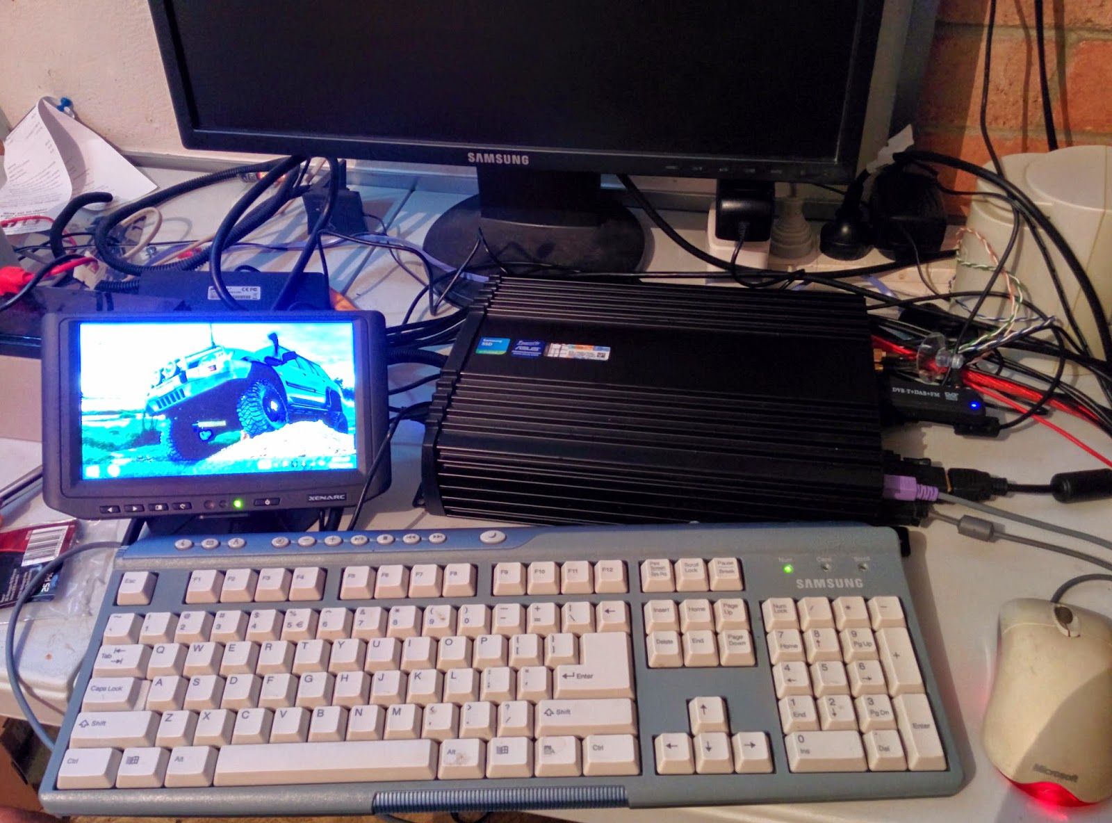 |
| Testing set-up, the larger monitor in the background is no longer needed |
Adjusting windows to work properly with the display took a little bit of tweaking but overall it was a relatively simple process. Getting the resolution correct was somewhat challenging, as the monitor's native resolution of 1024 by 600 pixels was not supported by the Intel HD graphics chip build into the computer's CPU. However the screen supports many different resolutions, so to work around this I set the resolution to 1920 by 1080 (1080P HD) and then configured windows to have extra large (250%) Windows and text for easy use on the touchscreen. Interestingly when I tested the screen at 1280 by 720p resolution, windows disabled the mobile (RT) apps stating that the resolution was too low to run them. Strange.
I made the mistake of installing the touchscreen's supplied touch driver software, however this was not needed as the driver software (which comes with a fully featured software suite) emulates a USB mouse and therefore Windows would not recognize it as a touchscreen. This meant that all the touch features native to windows 8.1 would not work. To fix this I simply uninstalled the drivers and software suite and let windows automatically install generic drivers. From then on I had full multi touch support and access to the gesture based windows features.
Using the touch screen feels as responsive and smooth as as using a brand new Android or iDevice. Being capacitive, no pressure on the screen is needed to register a touch, and multitouch pinching and zooming works flawlessly. I have no regrets in spending the extra money on this monitor over inferior resistive touchscreen technology though I do believe Xenarc has the monopoly as it was the only capacitive one I could find.
The monitor's built in OSD (on screen display menu) has a few handy features, other than the standard brightness, color & contrast adjustments; you can disable the hardware buttons on the front of the screen, disable the extra (VGA, RCA, ect) Inputs, turn on or off the automatic brightness adjustment, and tweak many other features.
Testing the screen with Google Chrome was a pleasant surprise, as Chrome has inbuilt touch-screen support. Pinch to zoom, forward and back navigation by swiping and easy tab changing are all supported.
 |
| Chrome running on the touchscreen |
To improve its ease of use, I installed an extension called Speed Dial 2. Its basically a replacement homepage that lets you configure it to have links to your favourite websites with large icons (pictured above).


No comments:
Post a Comment